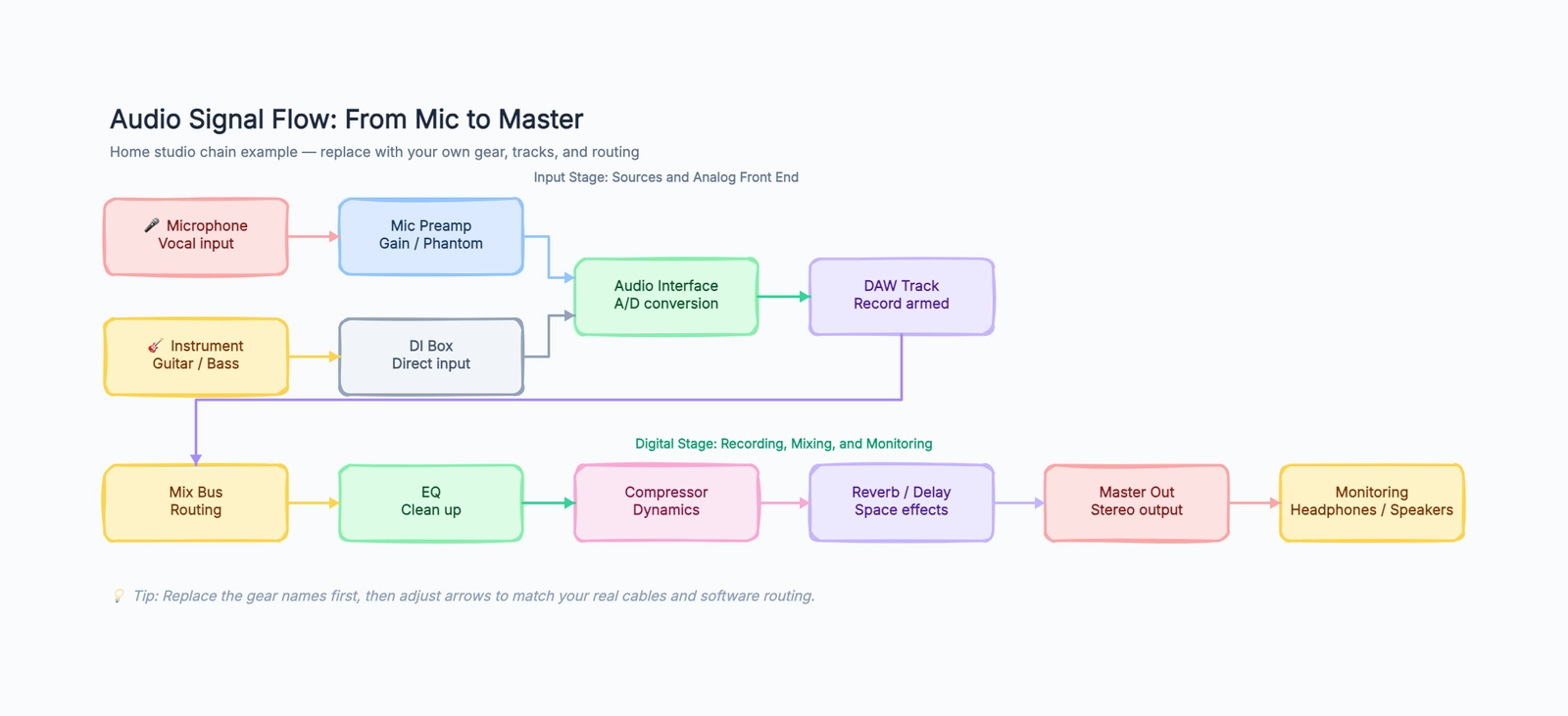
An audio signal flow diagram traces the invisible path your sound takes from the moment it leaves a microphone or instrument to the moment it reaches your ears through monitors or headphones. If you have ever stared at your audio interface and DAW wondering why there is no sound — or why there is sound but it sounds wrong — a signal flow diagram is what you need to draw before you can fix it.
This article walks through a complete audio signal flow for a home studio recording chain. It covers the analog input stage, the digital processing stage, and the output monitoring stage, with each piece of equipment labeled and connected by directional arrows. Open the free audio signal flow template to follow along.
The Three Stages of Audio Signal Flow
Think of signal flow in three stages: input, processing, and output. Most troubleshooting starts by asking which stage the signal disappears in.
Input Stage (Analog)
The input stage covers everything before the audio signal becomes digital. It starts at the sound source and ends at the audio interface's analog-to-digital converter.
Microphone path: sound waves hit the microphone diaphragm → mic-level electrical signal travels through an XLR cable → signal reaches the preamp, which boosts it to line level → boosted signal enters the audio interface.
Instrument path: electric guitar or bass → instrument cable → DI box or hi-Z input on the interface → converted to a balanced line-level signal.
Key decision: gain staging. The preamp gain knob controls how much the signal is amplified before it reaches the converter. Too low, and the noise floor competes with your signal. Too high, and you get digital clipping that cannot be fixed later. Aim for peaks around -12 dBFS to -6 dBFS on your DAW meters.
Processing Stage (Digital)
Once the signal is converted to digital, it enters the DAW. This is where most of the routing complexity lives.
Track: the recorded audio sits on a track in your DAW. At this point, the signal is a clean, unprocessed recording (unless you recorded through plugins).
Bus: tracks are routed to a bus — a virtual mixing channel that sums multiple tracks together. A typical session has a drum bus, an instrument bus, a vocal bus, and a mix bus that sums everything. Buses let you apply processing to groups of tracks instead of individual tracks.
Effects chain: on the bus or individual tracks, the signal passes through insert effects in series: typically EQ first (to cut unwanted frequencies), then compression (to control dynamics), then time-based effects like reverb and delay (via aux sends, not inserts — reverb on an insert washes out the dry signal).
Master bus: the final stereo sum of all buses and tracks. The master bus is where you apply mix-bus processing: subtle EQ for tonal balance, gentle compression for glue, and a limiter for loudness.
Output Stage
D/A conversion: the mastered digital signal is converted back to analog by the interface's digital-to-analog converter.
Monitoring: the analog signal goes to your monitor outputs — either powered studio monitors or a headphone amplifier. This is the sound you actually hear.
Common Signal Flow Problems and How to Trace Them
Use this checkpoint table before changing plugins or replacing gear:
| Symptom | First checkpoint | Next checkpoint | Likely fault domain |
|---|---|---|---|
| No input meter movement | Microphone or instrument | Preamp and interface input | Cable, power, input selection |
| Interface meter moves, DAW is silent | DAW input assignment | Record-arm and monitoring | Digital routing |
| DAW meter moves, headphones are silent | Master output | Interface output and mixer | Monitoring path |
| Clean input, distorted playback | Track and bus meters | Master meter | Plugin or bus gain |
| Delay while monitoring | Direct-monitor setting | Buffer size and plugins | Monitoring configuration |
Move left to right and stop at the first failed checkpoint. Changing several settings at once destroys the evidence that tells you where the signal stopped.
No sound at all. Start at the source and work forward. Is the mic cable plugged in? Is phantom power on (for condenser mics)? Is the preamp gain turned up? Is the track record-armed in the DAW? Is the track output routed to the master bus? Is the master output routed to your monitor outputs? One of these is the break in the chain.
Sound but it is distorted. Check gain staging. Is the preamp clipping (red light on the interface)? Is the track clipping in the DAW (red on the meter)? Is a plugin adding too much gain? Is the master bus clipping? Digital clipping at any stage is permanent damage.
Hearing an echo or slap-back. You are monitoring through the DAW with latency. Either reduce the buffer size in your DAW settings, or use direct monitoring on your interface (which routes the input signal directly to the headphones before it goes through the computer).
Only hearing sound in one ear. Check your track's pan setting in the DAW. If it is centered, check whether the track was recorded in stereo but is playing back on a mono channel — you may be hearing only the left channel. Also check the headphone cable and adapter; a partially inserted 1/4" adapter is a surprisingly common cause of one-ear audio.
How to Use the Signal Flow Diagram for Different Recording Scenarios
Recording a single vocalist. The chain is straightforward: mic → preamp → interface → DAW track. No bus routing needed. Apply EQ and compression as insert effects on the track. Skip the mix bus processing until mixing. The signal flow diagram helps you verify that every link in this short chain is active — phantom power on, preamp gain set, track record-armed.
Recording a full band live. Multiple microphones and DIs feed into the interface simultaneously. Each input gets its own track in the DAW. After recording, route all drum tracks to a drum bus, all instrument tracks to an instrument bus, and all vocal tracks to a vocal bus. Each bus gets its own EQ and compression. The buses sum to the mix bus, which feeds the master output. Draw this routing on the diagram before the session so the engineer and the band agree on the signal path.
Mixing with outboard gear. If you use hardware compressors or EQs, the signal leaves the DAW through an output on your interface, passes through the outboard processor, and returns through an input. This creates an analog insert loop. Draw this loop on your signal flow diagram, noting which interface outputs and inputs are used, so you can recreate the routing in future sessions.
Podcast or spoken word recording. The chain is simpler than music: mic → preamp → interface → DAW track → master output. The key differences: you typically record in mono, you may need a cloudlifter or inline preamp for dynamic mics like the SM7B, and processing (EQ, compression, de-esser) is often applied during recording rather than during a separate mixing stage. A signal flow diagram for podcasting also helps troubleshoot the most common issue: the host cannot hear themselves because the monitoring path is not configured.
Reading a Signal Flow Diagram Left to Right
A well-drawn audio signal flow diagram always reads left to right: source on the left, destination on the right. This convention matches how we read text and makes the diagram intuitive for anyone who picks it up. When you draw your own diagram, maintain this direction. If you have a feedback path or a send/return loop, draw it as a separate line that loops back — do not reverse the main flow direction. A consistent left-to-right flow is the difference between a diagram that clarifies and a diagram that confuses.
Also separate parallel sources before they merge. A vocal mic and an electric guitar do not have to share the same first few boxes: the mic usually goes through a preamp, while the guitar may go through a DI or hi-Z input. Draw those as two short lanes that merge at the audio interface. This keeps the diagram honest and makes troubleshooting faster, because you can isolate one lane without mentally untangling the other.
Analog vs. Digital: Where the Real World Meets the Computer
Understanding where analog ends and digital begins is the key to troubleshooting. The analog domain (everything before the interface's A/D converter) is where physical problems live: bad cables, ground hum, impedance mismatches, phantom power issues. The digital domain (everything after the converter) is where routing and processing problems live: buffer underruns, plugin latency, bus misconfiguration, clipping from excessive plugin gain.
A useful practice: draw a vertical dashed line on your signal flow diagram between the interface and the DAW. Label the left side "Analog — check cables, gain, and power." Label the right side "Digital — check routing, buffers, and plugin gain." When something goes wrong, this line tells you which half of the diagram to investigate first. Most beginners waste time checking digital settings when the problem is a bad XLR cable, or swapping cables when the problem is a misrouted bus.
Building Your Own Signal Flow Diagram
Start with the free template and customize it for your setup:
- List every piece of gear in signal chain order. Include cables and connection types (XLR, 1/4" TS, 1/4" TRS, USB, Thunderbolt) — the connector type often explains compatibility issues.
- Note gain staging points. Mark every knob or fader that controls signal level: preamp gain, interface input gain, track fader, bus fader, master fader. These are your troubleshooting checkpoints.
- Mark where the clock comes from. In a digital setup, one device must be the clock master. Usually it is the audio interface. If you have multiple digital devices connected via ADAT or S/PDIF, note the clock source on the diagram — clock mismatches cause clicks, pops, and dropouts.
- Label every output. Where does each physical output on your interface go? Output 1-2 → studio monitors, Output 3-4 → headphone amp, Output 5-6 → outboard compressor. If you unplug your setup and need to reconnect it, the diagram should tell you exactly what goes where.
Open the free audio signal flow diagram template, replace the pre-filled gear with your own equipment, and trace your signal chain from source to ears.