An assembly line diagram answers one question before you spend a dollar on tooling: in what order does this product come together, and what does each step hand to the next? It is the fastest way to see a line's flow — and its bottlenecks — without a drawing package, a floor plan, or a meeting full of hand-waving.
Here is the short version: list the stages left to right, give each station a number and a process name, write what it takes in and what it sends out, and draw an arrow between every pair. Five steps, three scenes in the assembly line diagram template, and you have a line you can edit, share, and argue over productively. This guide walks through each step, then shows the same structure applied to a car, an electronics device, and a piece of furniture.
What an assembly line diagram is (and isn't)
An assembly line diagram is a linear sequence of workstations, not a picture of a building. Each station is one step — stamp, weld, assemble, test — and each carries three pieces of information: the process it performs, the input parts it receives, and the output it hands off. Arrows connect the stations in flow order.
That last point is where people confuse it with two other drawings. A factory layout is a top-down floor plan showing where zones and machines sit in physical space — the material dock here, the paint booth there. An assembly line diagram does not care where anything sits; it cares what happens in what order. If you need the spatial view, the factory layout template is the right tool. A process flowchart, meanwhile, handles decisions and branches — "does this pass inspection?" with a yes and a no path. An assembly line is mostly linear, so it trades the diamonds for a clean left-to-right handoff.
The five parts every assembly line diagram needs
Every station, whatever the product, is built from the same five pieces:
- A station number — so the sequence reads 1, 2, 3 without anyone asking.
- A process label — a verb or short phrase: stamping, welding, SMT placement, edge banding.
- Input parts — the material or sub-assembly arriving at the station.
- An output — what the station produces and passes on.
- A flow arrow — pointing from this station to the next, so direction is never ambiguous.
The trick is that each station's output should become the next station's input. A car line passes panels out of stamping and into welding, then a body-in-white out of welding and into painting. When the handoff lines up this way, the diagram is self-explanatory — you can read it left to right and understand the whole build without a single annotation.
How to map an assembly line diagram in 5 steps
1. List the stages in order
Start with the product and write its stages in the order they actually happen. Resist the urge to group by department or by machine — the diagram follows the part, not the building. For a car, that is stamping, welding, painting, assembly, and final inspection. For furniture, cutting, edge banding, drilling, and packing.
2. Name each station
Give every stage a number and a process name. Keep the name to a verb or short phrase so it fits on a card: "3 · Painting", "2 · Soldering". The number does the ordering work; the name tells you what happens there.
3. Add the inputs and outputs
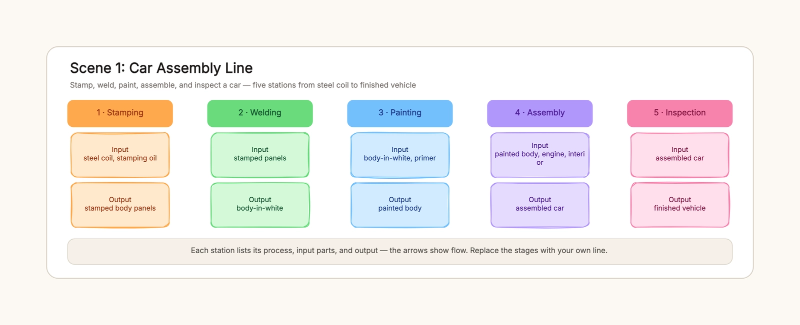
Under each station, list what arrives and what leaves. Stamping takes steel coil and stamping oil and produces body panels. Assembly takes a painted body, an engine, and interior parts and produces a finished car. Writing both forces you to notice the one station whose output has nowhere to go — usually a sign you missed a step.
4. Connect the stations with arrows
Draw an arrow from each station to the next, pointing in the flow direction. Keep the sequence strictly left to right so the arrows never cross. A crossed or backtracking arrow usually means a station is out of order, not that the process is wrong.
5. Check the handoff and share
Walk the line once and confirm each station's output matches the next station's input. Then share the board. The whole point of doing this on a whiteboard rather than in CAD is that you can drag a station, rename a step, and split an overloaded card live in a review meeting — and the team can see the change immediately.
A car assembly line, end to end
The car scene in the template is the most complete example, so it is worth walking through as a model for your own line.
Stamping takes steel coil and stamping oil and turns out body panels — the outer skin of the car. Welding joins those panels into a body-in-white, the unpainted metal shell. Painting applies primer and color to the shell. Assembly is the busiest station: it takes the painted body, drops in the engine, and installs the interior to produce a complete car. Final inspection checks the finished vehicle and releases it.
Notice what each station's output is: panels, body-in-white, painted body, assembled car, finished vehicle. Every one of those is the next station's input. That is the property that makes the diagram read cleanly, and it is the property you should preserve no matter what product you are mapping. If you also need to show where these stations sit on a real floor, that is the separate job of a factory layout — the two views answer different questions.
The same line, different parts: electronics and furniture
Once you have the structure, other products are just a matter of swapping names and materials.
An electronics line runs a device from a bare PCB to a boxed product in four stations. SMT placement populates the board with components; soldering secures the through-hole parts; assembly fits the board into a housing with a screen; testing and packing verifies the unit and boxes it with its power adapter. The input on the first station is a bare board, and the output on the last is a shippable product.
A furniture line turns sheet board into flat-pack units. Cutting produces the pieces, edge banding applies the edge tape, drilling adds the assembly holes, and the final station assembles and packs the panels with their hardware. The hardware list on that last station is where furniture lines differ most, which is why it stays explicit rather than being folded into "packing".
What changes between these scenes is the parts, not the pattern. The linear station sequence, the input/output cards, and the flow arrows stay identical. That is the value of a template over a blank canvas: you are not redrawing the idea of a line, you are editing one instance of it.
Assembly line diagram vs. factory layout
The confusion between these two is common enough to deserve its own section, because choosing the wrong one produces a drawing nobody can use.
An assembly line diagram answers "what happens, in what order?" It is a sequence of stations connected by arrows, and it fits on a screen or a printed page without a scale. It is what you want when you are designing the process, balancing the work between stations, or explaining to a new hire how a product is built.
A factory layout answers "where does everything sit?" It is a top-down floor plan with zones — receiving, the line itself, quality control, the warehouse — and it needs a building footprint and a sense of scale. It is what you want when you are leasing space, placing machines, or planning material flow through the room.
Most teams need both, but at different moments. Start with the assembly line diagram to get the process right, then move to the factory layout template once the sequence is settled and you need to place it in a real space. Drawing a floor plan first and trying to read the process out of it is the most common reason a line diagram ends up scrambled.
Common mistakes that make a line diagram useless
Skipping inputs and outputs
A station with no input or output hides where its parts come from and where they go. The whole point of the diagram is the handoff — leave it out and you have a list of names, not a line.
Breaking the left-to-right order
When stations wander out of order, the arrows cross and the flow becomes a puzzle. Keep it strictly left to right, and treat a crossed arrow as a signal that a station is misplaced.
Treating zones as stations
"Mixing" and "assembly" can be zones on a floor, but on a line diagram they should be steps. If you find yourself drawing a room, you have drifted into factory-layout territory — which is fine, just use the right template for it.
Overloading one station
Cramming stamping, welding, and painting into a single card hides the real bottleneck. A station should be one meaningful step. If it is doing three unrelated things, split it and re-check the handoff.
No arrows
Without arrows, the direction is a guess. Point every connector at the next station so the flow is unambiguous even to someone seeing the diagram for the first time.
Keep the line honest as it changes
An assembly line is never finished the day you draw it. A machine breaks, a supplier changes a part, a station gets merged with its neighbor. Because the diagram lives on an editable whiteboard rather than in a static document, keeping it honest is a five-minute job: drag the changed station, update the input card, and the arrows re-route themselves.
Review it when the product changes, not just when you build a new line. A line that matches reality is the one people actually pull up in a meeting; a line that drifted out of date is the one they quietly ignore. Start from the assembly line diagram template, replace the stations and parts with your own, and you will have a diagram that earns its place on the wall — and, more importantly, in the next planning conversation.