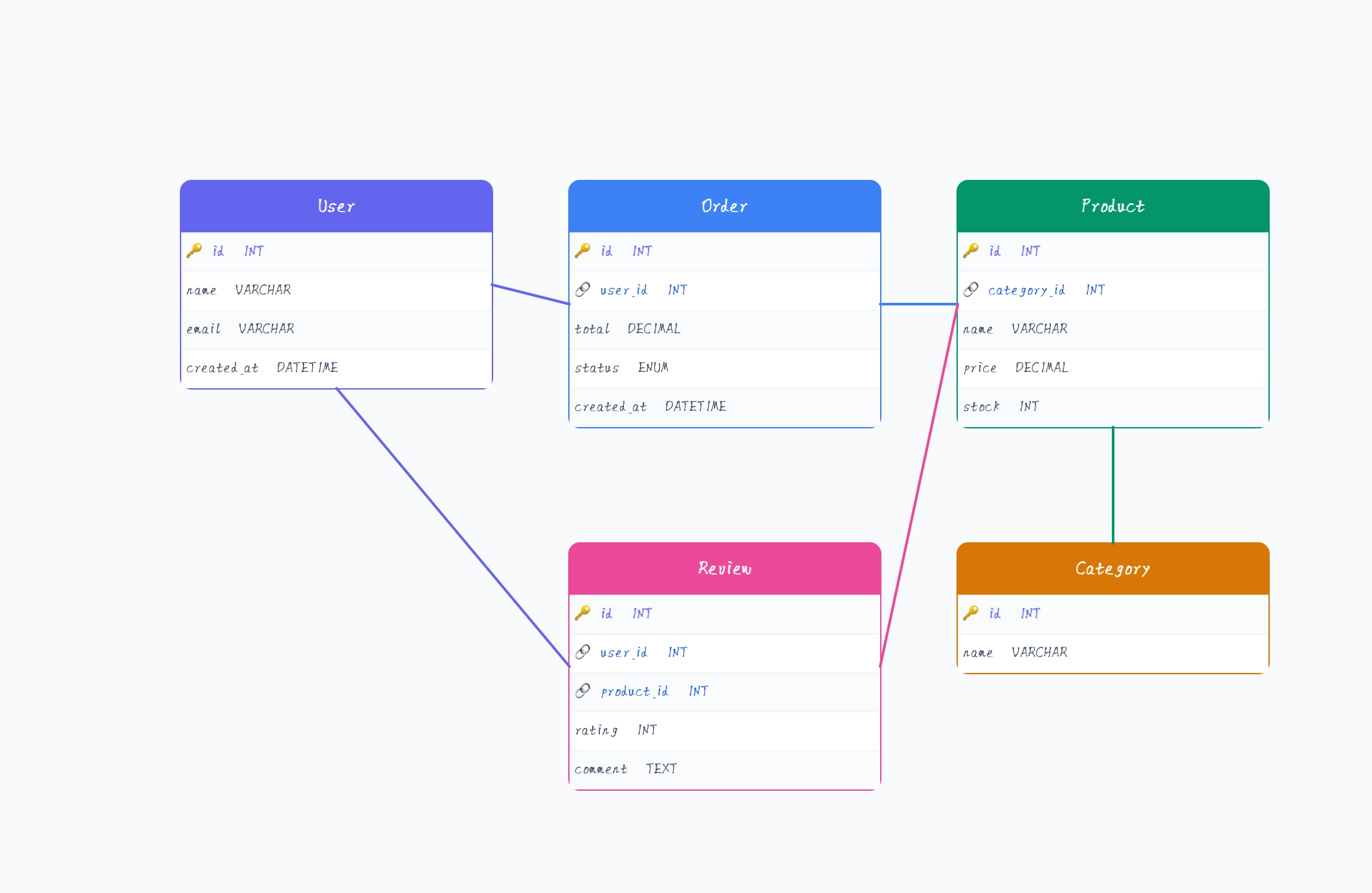
Back to template

ER Diagram Examples

These ER diagram examples show the table structures and relationships that developers encounter most often. Each one covers a real application domain so you can see how entities connect and adapt the schema to your own project.

ER Diagram Examples

Real examples

E-commerce schema

Who uses it: Backend developer or architect designing an online store database

Customer (id PK, email, name, created_at)
Address (id PK, customer_id FK, street, city, country)
Product (id PK, name, price, category_id FK, stock)
Order (id PK, customer_id FK, address_id FK, status, total)
OrderItem (id PK, order_id FK, product_id FK, quantity, unit_price)
Category (id PK, name, parent_id FK)

Why this works: Separating Address from Customer and OrderItem from Order keeps the schema normalized — a customer can have multiple addresses and an order can contain multiple products without duplication.

Multi-tenant SaaS schema

Who uses it: Full-stack developer designing a B2B SaaS with multiple client accounts

Organization (id PK, name, plan, created_at)
User (id PK, org_id FK, email, role)
Project (id PK, org_id FK, name, status)
Task (id PK, project_id FK, assignee_id FK, title, due_date)
Comment (id PK, task_id FK, user_id FK, body, created_at)
AuditLog (id PK, org_id FK, user_id FK, action, created_at)

Why this works: Every table carries an org_id foreign key so all queries can be scoped to a single tenant — the ER diagram makes the isolation boundary explicit before any code is written.

Blog or CMS schema

Who uses it: Developer building a content management system or headless CMS

Author (id PK, name, email, bio)
Post (id PK, author_id FK, title, body, status, published_at)
Tag (id PK, name, slug)
PostTag (post_id FK, tag_id FK) — junction table
Comment (id PK, post_id FK, author_name, body, approved)
Media (id PK, post_id FK, url, type, alt_text)

Why this works: The PostTag junction table handles the many-to-many relationship between posts and tags without repeating tag data in every post row — a common schema pattern worth making explicit in the diagram.

Hospital management schema

Who uses it: Developer or analyst building a healthcare records system

Patient (id PK, name, dob, gender, contact)
Doctor (id PK, name, specialty, department_id FK)
Department (id PK, name, location)
Appointment (id PK, patient_id FK, doctor_id FK, date_time, status)
Prescription (id PK, appointment_id FK, medication, dosage)
Billing (id PK, appointment_id FK, amount, paid_at)

Why this works: Tying Prescription and Billing to Appointment rather than directly to Patient means all clinical and financial records are traceable to a specific visit — important for auditing and compliance.

Social network schema

Who uses it: Developer building a social app with follows, posts, and reactions

User (id PK, username, email, avatar_url)
Follow (follower_id FK, following_id FK) — junction table
Post (id PK, user_id FK, body, created_at)
Like (user_id FK, post_id FK) — junction table
Comment (id PK, post_id FK, user_id FK, body)
Notification (id PK, user_id FK, type, ref_id, read)

Why this works: The Follow table is a self-referencing many-to-many on User — drawing it in the ER diagram makes it clear that follower and following are both foreign keys into the same table.

Inventory management schema

Who uses it: Developer building a warehouse or stock management system

Product (id PK, sku, name, category_id FK, unit_cost)
Warehouse (id PK, name, location)
Stock (id PK, product_id FK, warehouse_id FK, quantity)
Supplier (id PK, name, contact, lead_days)
PurchaseOrder (id PK, supplier_id FK, status, expected_date)
POItem (id PK, po_id FK, product_id FK, quantity, unit_price)

Why this works: The Stock table is a junction between Product and Warehouse — modeling it explicitly allows the same SKU to be tracked independently across multiple warehouse locations.

Tips for better study mind maps

  • Always show the primary key and foreign keys in each entity box — the relationships are only half the story without knowing which field carries the reference.
  • Use crow's foot notation consistently for cardinality: the fork end goes on the many side, the single line on the one side.
  • Draw many-to-many relationships through an explicit junction table even in the conceptual diagram — it avoids confusion when the physical schema is implemented.
  • Keep attribute lists short in the diagram — show only keys and a few important fields; a full column list belongs in the schema documentation, not the ER diagram.

Start editing online

Go back to the template, swap in your own topics, and keep the same structure if it fits your class or project.

Use this template: /editor/new?template=erd

Use this template